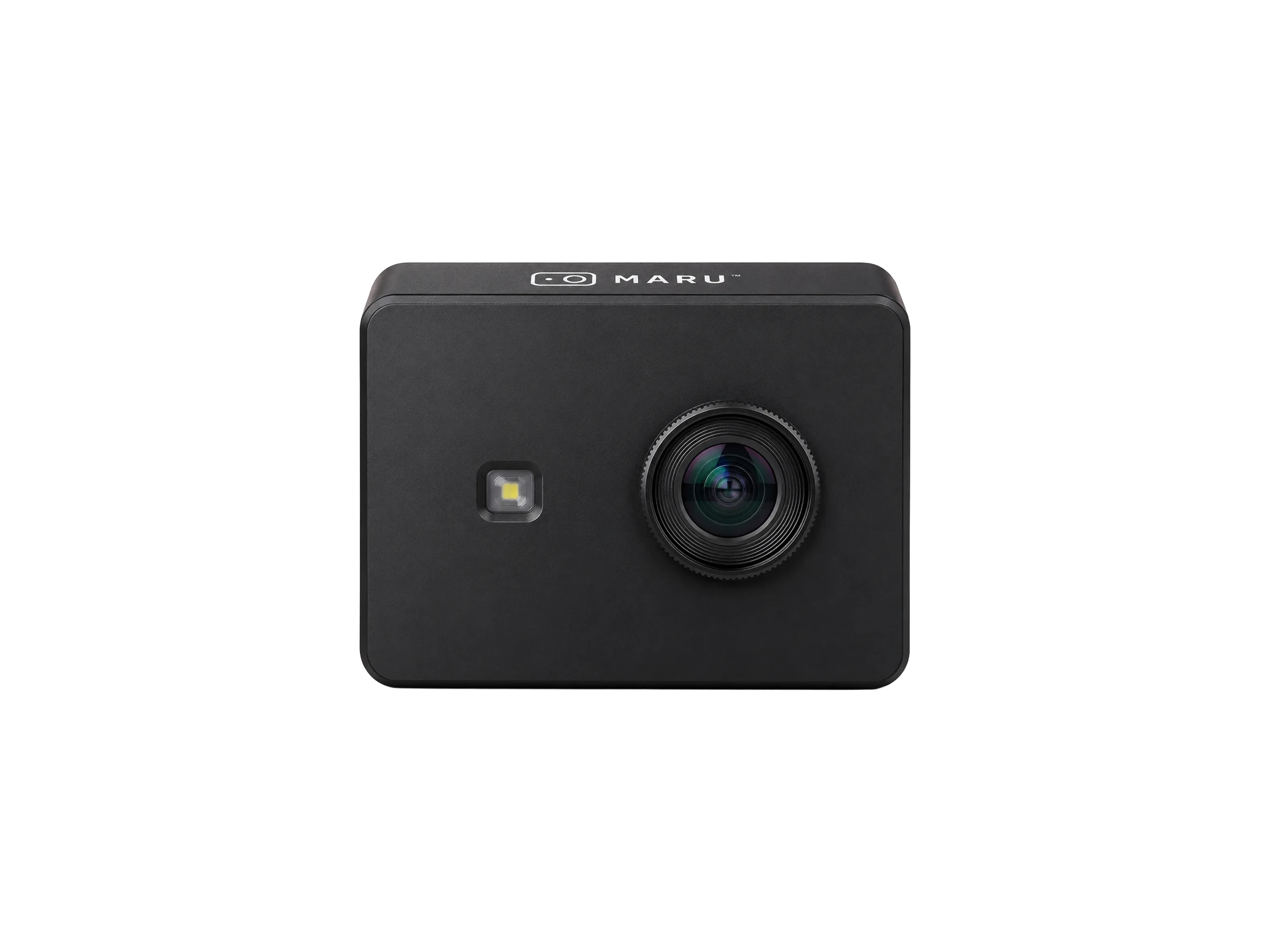
Sensor stage
Vision or ToF optics on the top face.
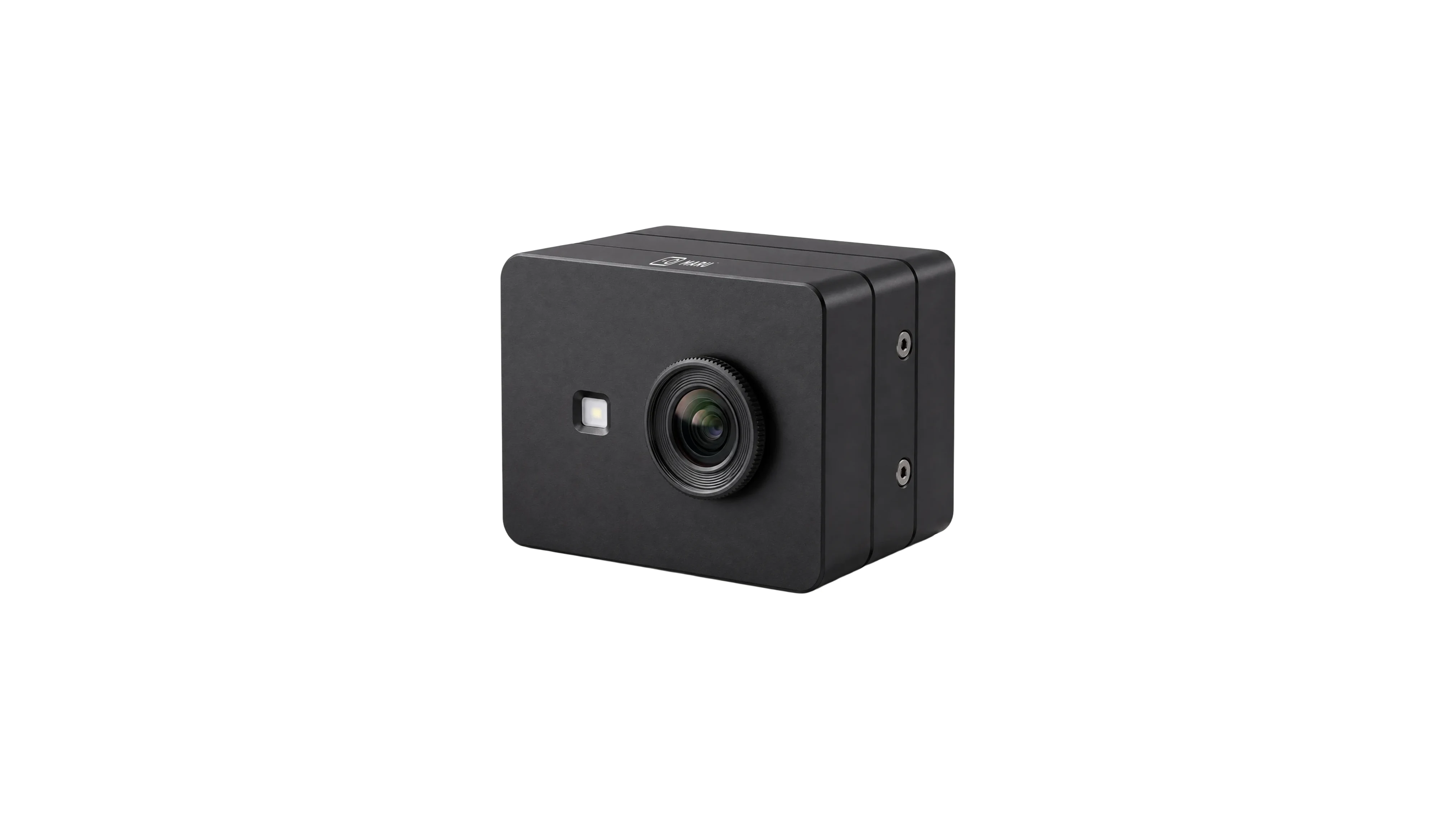
MARU Gen 2 · assembled, vertical

The same blocks stacked instead of chained. Sensor, edge, and interface stages sit on one vertical axis, so the installed area is the area of one stage.
Why vertical
In a machine cell the scarce dimension is rarely height — it is bracket area, cabinet width, the free space beside a conveyor. Tower puts the same optics and the same edge compute on a vertical axis so the mount stays small.
Because the stages are the platform's stages, everything downstream is unchanged: the same calibration, the same SDK, the same ROS 2 topics as Link and ONE.
opticscomputeI/OStages
Vision or ToF optics on the top face.
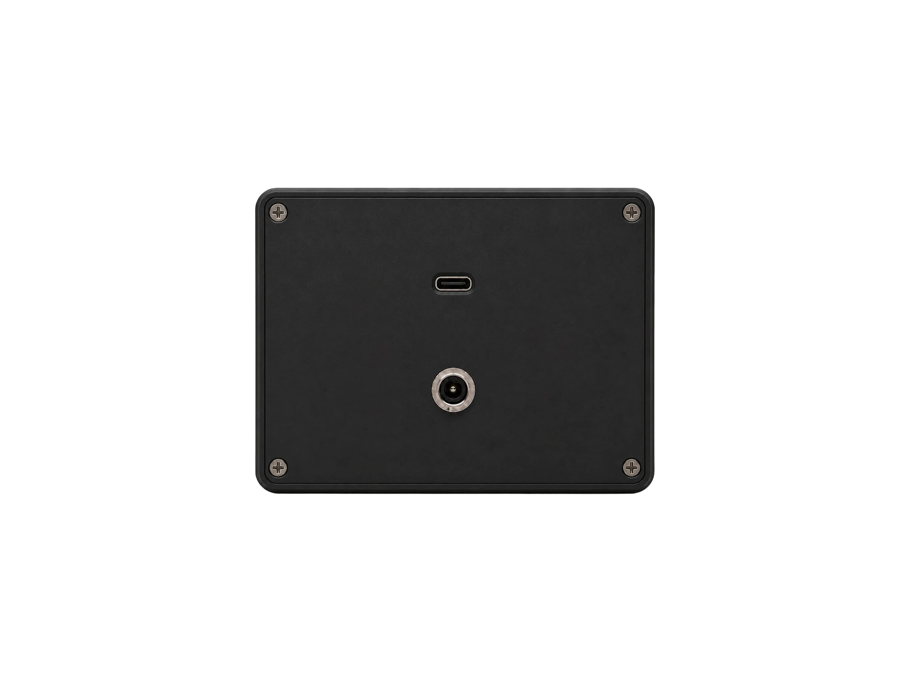
On-device inference and calibration.
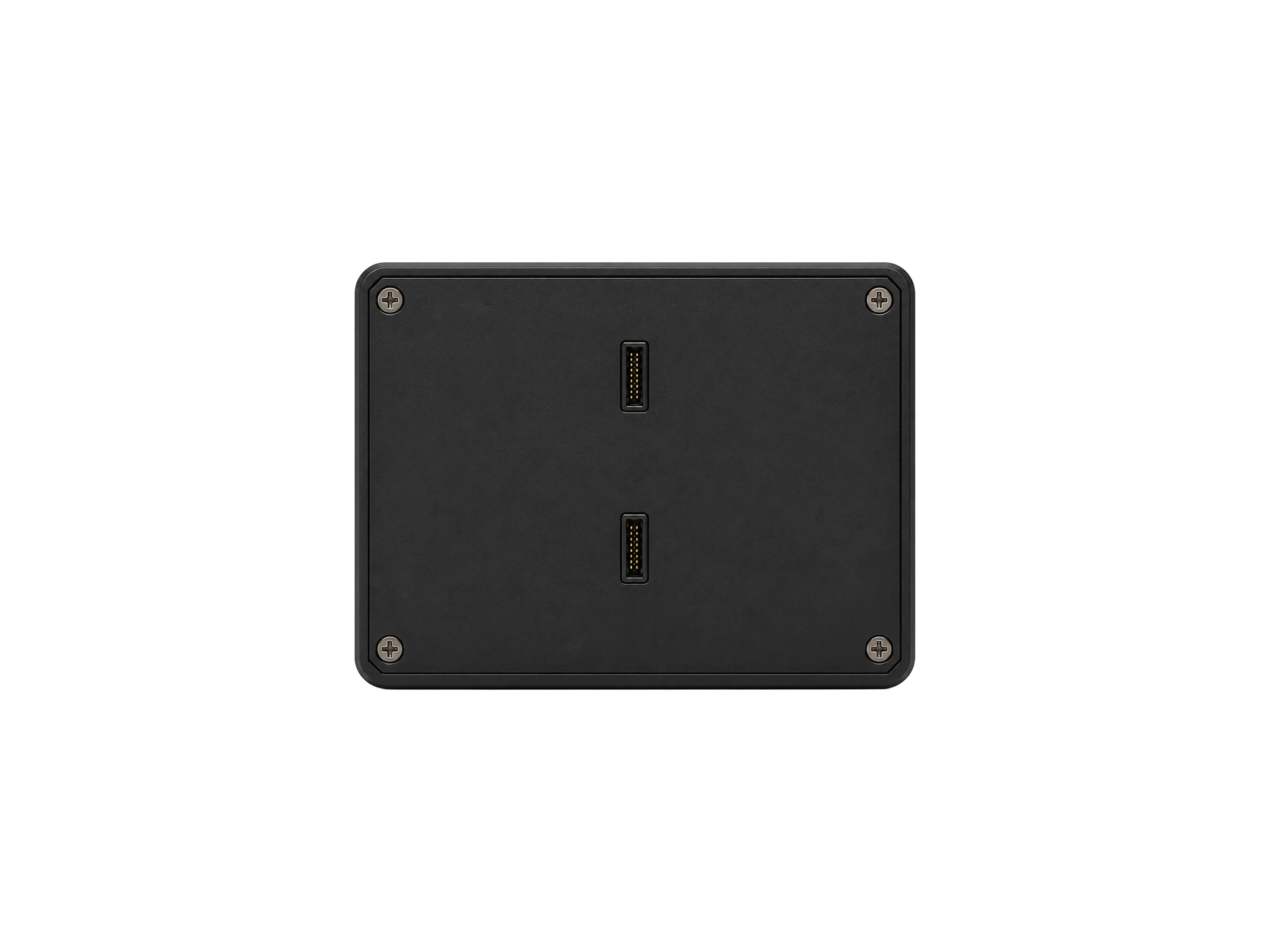
Power and the host link for the chosen bus.
Specifications
| 3D depth | ToF · VCSEL 940 nm · 0.2–20 m · ±0.5% |
|---|---|
| 2D imaging | RGB + IR · 5 MP–8K · 45–155° diagonal FoV |
| Frame rate | 30–60 FPS |
| Edge compute | Runs across edge SoCs · 10–100 TOPS · 10–20 ms on-device |
| Interfaces — HW | USB-C Ethernet SerDes HDMI/DP |
| Interfaces — SW | ROS 2 · REST/SDK API |
| Delivered as | Sensor + edge AI + I/O on one calibrated platform · Ruggedized field housing · factory-calibrated |
Downloads
Datasheet, mechanical drawing, and SDK guide ship with the production revision. Ask us for the current draft.